
Construction and Installation
Massive Natural-Stone Construction and Load-Bearing Masonry
Understand how stone becomes structure: load-bearing walls, masonry bonding, quarry beds, corners, openings, arches, vaults, mortars, stability, moisture, construction, defects and restoration.
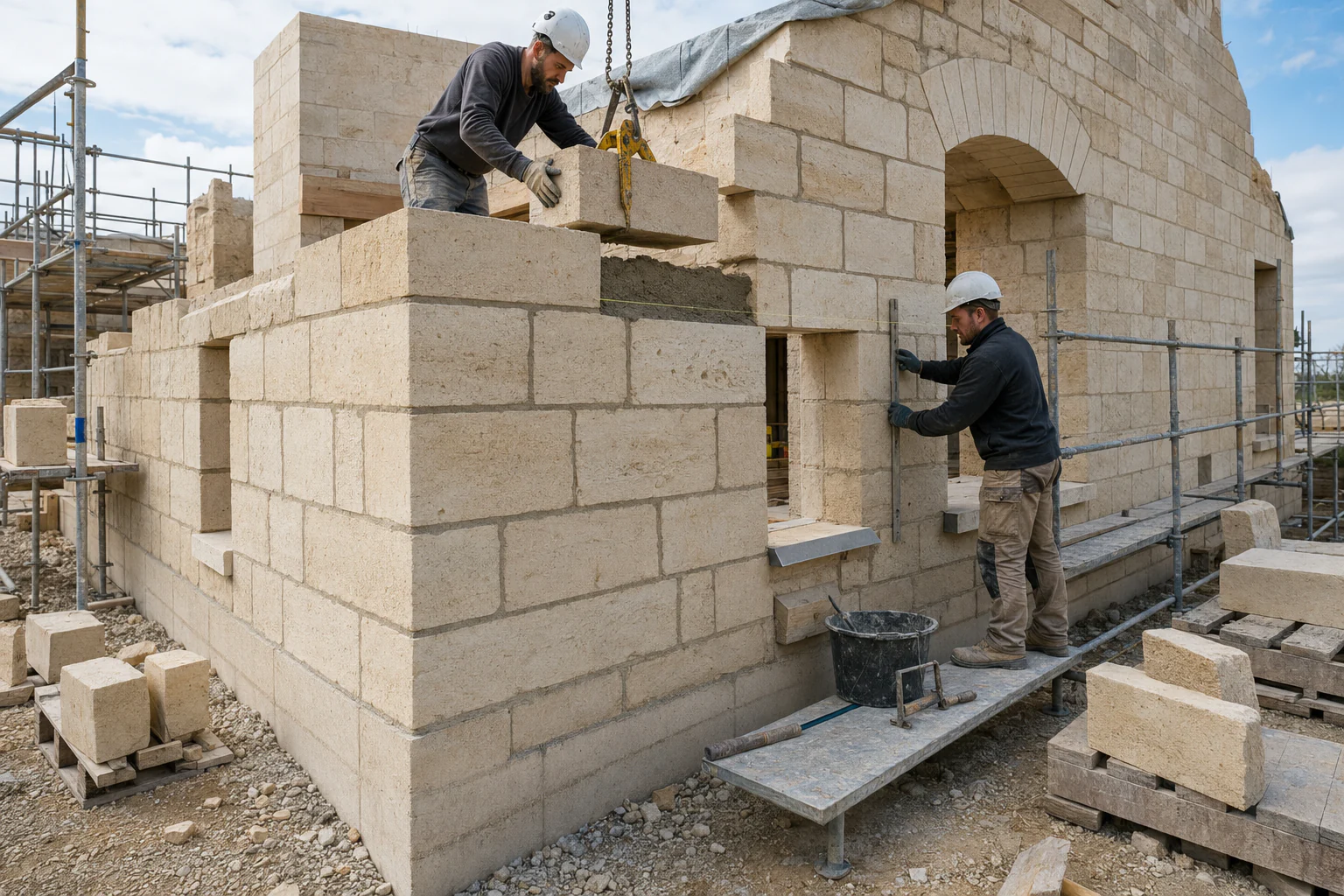
When stone genuinely carries the building
Load-bearing stone masonry carries its own weight and the building loads and transfers them to the foundations. It may form a wall, pier, arch, vault, staircase or structural element. Its behaviour differs fundamentally from thin bonded cladding or mechanically fixed stone façades applied to an independent structure.
This distinction governs the entire project. Cladding stone is assessed primarily for fixing, façade actions and weathering. Structural stone must also be characterised for compression, directional defects, bed geometry, load transfer and overall stability. Appearance alone can never establish structural suitability.
Stone generally performs well in compression but is far weaker in tension and bending. Design therefore aims to keep forces within the masonry thickness, provide adequate bearings and avoid stress concentrations. Loads, height, slenderness, openings, wind, seismic action, floors and ground conditions must be considered together.
| System | Role of the stone | Primary checks |
|---|---|---|
| Massive load-bearing wall | Vertical structure and envelope | Strength, stability, connections, moisture and thermal performance |
| Rubble-stone masonry | Wall built from more irregular units | Core, through-stones, mortar, integrity and thickness |
| Coursed ashlar masonry | Geometrically defined load-bearing courses | Natural bed, joints, bearings and cutting accuracy |
| Mechanically fixed cladding | Non-load-bearing skin | Anchors, cavity, joints and façade actions |
| Bonded finish | Surface finish | Substrate, adhesive, format, moisture and compatibility |
Anatomy of a stone wall
A historic wall may be homogeneous stone throughout its thickness or have two faces tied around an internal rubble core. Contemporary walls may use large solid blocks, pre-cut units or hybrid stone-and-frame systems. In every case, the visible faces alone do not describe the construction: the core and transverse connections are critical.
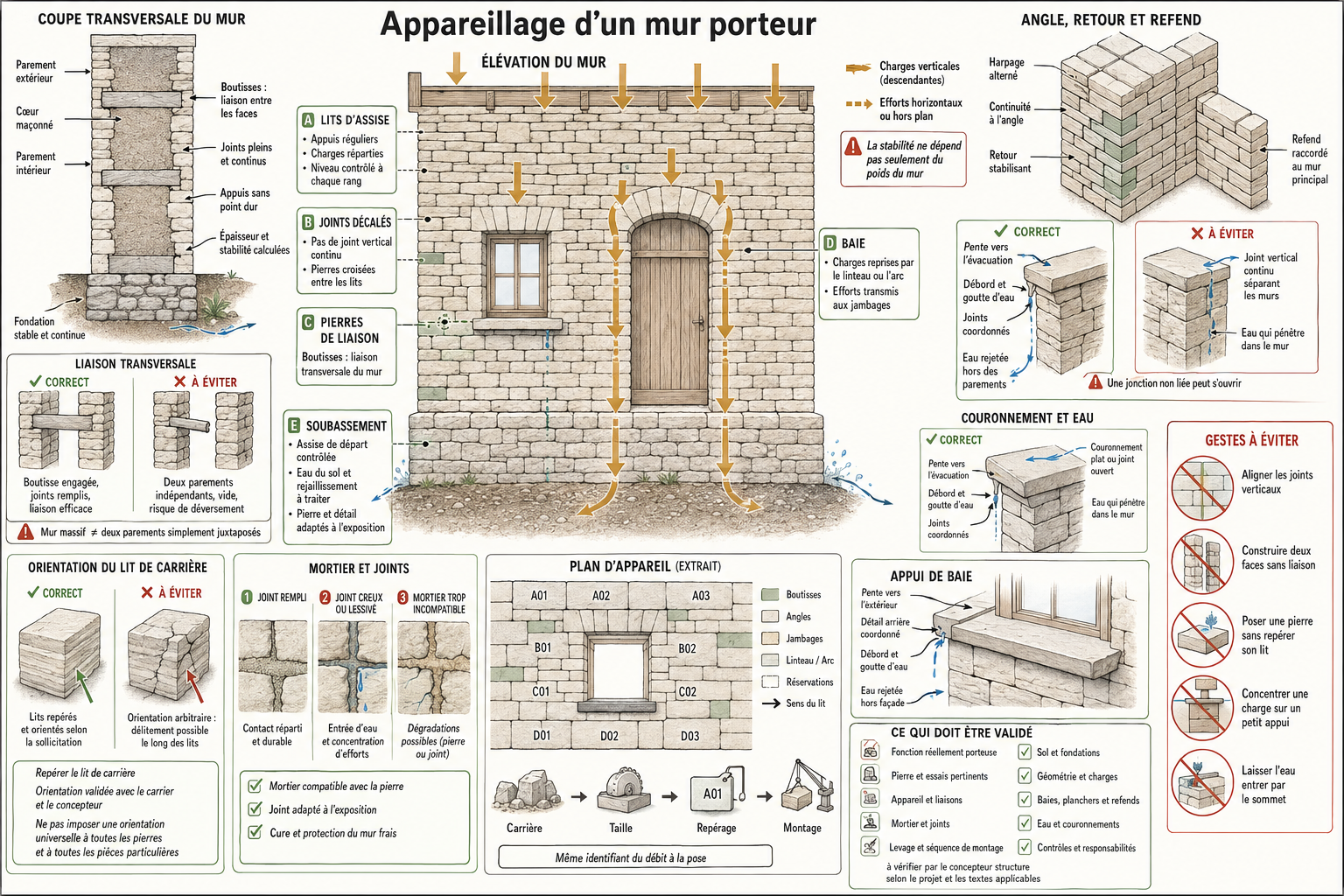
A course is a horizontal row. The bed is the face on which a stone rests; bed joints separate courses and vertical joints separate units in the same course. A stretcher presents its length along the wall. A header extends further through the thickness and helps tie the faces together. A through-stone connects the full wall thickness.
The plinth receives splash water and impact. Quoins, jambs, string courses, cornices and copings have an architectural role but may also organise forces and protect the building. They must be designed as construction, not applied decoration.
Quarry bed and stone orientation
Sedimentary rocks formed through successive deposits and may contain bedding, laminations, stylolites, fossils or weakness planes. Traditional construction often places stone on its natural quarry bed, with an orientation consistent with its formation and applied loads.
Placing stone off-bed means orienting it differently from its natural bedding. This may be deliberate for certain carved pieces or suitable limestones, but can also promote delamination, scaling or failure. Quarry operators, fabricators and designers must identify the rock structure and deposit-specific limits rather than rely on habit.
For anisotropic stone, test-specimen orientation must correspond to the direction of loading in the construction. Petrographic information, test data and block inspection complement quarry knowledge.
Bonding masonry so separate stones work together
Masonry bond describes how stones are cut, laid and alternated. Good bonding distributes loads, avoids continuous vertical joints, ties the wall thickness together and enables consistent construction. The stone layout expresses this logic on plans and elevations.
Vertical joints are staggered from course to course. Undersized units, point packing and long joint lines weaken both the appearance and behaviour of the wall. At corners and junctions, alternating units must create genuine interlocking bond. In a two-faced wall, headers or transverse ties prevent the faces separating from the core.
Ashlar requires sufficiently flat bearing faces and controlled course heights. Rubble masonry requires careful unit selection, stable placement, thorough filling of voids and control of irregular mortar thickness. Both seek a continuous load path without isolated hard points or hidden voids.
| Bonding detail | Function | Defect to avoid |
|---|---|---|
| Staggered joints | Distribute loads | Continuous vertical joints |
| Headers and ties | Tie the wall thickness together | Two independent faces |
| Regular courses | Create continuous bearings | Rocking stones or point packing |
| Interlocking corner bond | Tie two wall directions together | Simply abutted corner |
| Stone layout | Plan formats, joints and openings | Improvised cuts and small infill pieces |
Foundations, plinth and first course
Wall durability begins below the visible level. Foundations must transfer loads to understood ground, limit differential settlement and provide geometry compatible with the masonry thickness. Work to a historic building begins with investigation of the ground, deformation and successive alterations.
Set the first course carefully for level, bearing width, unit stability and continuous filling. The plinth is particularly exposed to rising moisture, salts, splash water and frost. Durable stone cannot compensate for trapped water at the wall base.
Drainage, ground levels, rainwater disposal, capillary breaks where technically and historically appropriate, and finish permeability must form a coherent strategy. Abruptly blocking moisture movement can displace deterioration rather than resolve it.
Corners, cross walls, floors and structural continuity
A load-bearing wall does not act alone. Stability depends on returns, cross walls, floors, roof and their connections. Properly interlocked corners and tied cross walls give the building three-dimensional behaviour; walls merely abutted may separate under movement or horizontal actions.
Floors and roof structures need sufficient bearing without locally crushing the stone. Concentrated loads may require a spreader, bearing block or specific detail. Added anchors and ties must work with the existing masonry without creating excessive local stiffness or promoting corrosion.
In seismic or highly wind-exposed areas, connection quality is essential. The strategy requires structural calculation within the applicable regulatory framework and cannot be inferred from a generic wall thickness.
Openings: jambs, lintels, arches and sills
An opening interrupts the load path. Jambs receive forces from the lintel or arch and transfer them to the courses below. Bearing width, stone quality, joints near the opening and any bearing block directly influence behaviour.
A stone lintel works in bending, making its span, depth, stone defects and loads above critical. An arch instead seeks to transfer forces mainly in compression to its supports. It requires precise geometry, correctly cut voussoirs, stable haunches and abutments capable of resisting thrust.
A window sill must shed water through its fall, upstands and drip. Junctions with frames and jambs must prevent ingress. A successful opening coordinates structure, water resistance and architectural detailing.
Arches, vaults and stereotomy
Stereotomy is the art of defining and cutting the volumes that form arches, vaults, squinches, staircases and complex stonework. Historical treatises describe setting-out drawings, surface development and the translation of geometry into each voussoir. Their contemporary value lies in this rigour: every stone has a defined position, orientation and contact faces.
Temporary centring supports units during construction. It must not be struck until the assembly can carry the forces, allowing for the construction system and mortar. Incorrect cutting, wedge-shaped joints or inadequate abutments alter the thrust line and may cause opening, rotation or cracking.
Digital tools can model, number and machine components, but do not replace structural understanding or allowance for site tolerances. Methodlling, cutting, lifting and assembly must use the same geometric reference.
Mortars and joints: working with the stone
Mortar fills irregularities, distributes contact, binds the masonry and influences moisture movement. Strength must not be selected in isolation: excessively hard, impermeable mortar can concentrate stress in soft stone, retain moisture and make repairs destructive.
In historic construction, lime-based mortars are often selected for mechanical and hygrothermal compatibility. Lime type, aggregate, proportioning and curing depend on the stone, exposure, joint thickness and required performance. In engineered new construction, mortar must match the specified system and applicable standards.
Joints must be fully filled where required, protected from rapid drying and finished without staining or sealing the stone. Their profile affects runoff. Repointing must not conceal cracking before movement and moisture are understood.
Understanding structural behaviour
Load-bearing masonry combines stones, joints and sometimes a heterogeneous core, so its strength is not that of a rock specimen alone. It depends on unit strength and shape, mortar, thickness, slenderness, eccentricity, workmanship, openings and support conditions.
An eccentric load can move the resultant outside the compressed zone and open a joint. Vault or roof thrust can spread walls. Differential settlement can produce diagonal cracking. Loss of transverse ties can cause bulging. These mechanisms must be understood before repair.
Design must follow relevant calculation rules, declared or measured properties and competent structural engineering where stability is involved. No single thickness, span or strength value suits every stone and building.
| Input | Why it matters | How to verify it |
|---|---|---|
| Stone type and orientation | Strength and weakness planes | Petrography, quarry information and tests |
| Compression | Capacity under vertical load | Appropriate testing and calculation |
| Wall geometry | Slenderness and eccentricity | Drawings, survey and calculation |
| Mortar and joints | Load distribution and deformation | Specification and site inspection |
| Connections | Out-of-plane stability | Construction details and inspection |
| Ground and foundations | Settlement | Site investigation and diagnosis |
Water, frost and copings
Water is a major cause of deterioration. It enters from the ground, driven rain, joints, copings, openings or services, carries salts, promotes biological growth and increases frost risk when stone is saturated.
The design must shed water before relying on surface treatment: sloping copings, overhangs and drips, correctly designed sills, reliable rainwater disposal, suitable plinths and maintained joints. Horizontal surfaces and junctions require more attention than ordinary vertical faces.
A water repellent cannot turn a poor detail into a good one. On historic masonry, compatibility and influence on drying must be assessed on a test area after the moisture source has been addressed.
Thermal comfort, acoustics, fire and environment
Stone mass provides thermal inertia and acoustic attenuation, but an uninsulated massive wall does not automatically satisfy modern energy targets. Insulation, thermal bridges, airtightness and vapour control must be designed without trapping moisture in sensitive masonry.
Stone is mineral and non-combustible, but fire resistance depends on the complete system: thickness, joints, mortars, connections, floors and stability under heating. Metal fixings and adjacent elements must also be considered.
Massive construction can use durable, repairable and reusable material, but environmental value depends on the real project: origin, block yield, fabrication energy, transport, material quantity, service life and dismantling or reuse strategy.
Building with massive stone today
Contemporary methods combine masonry knowledge with digital surveying, computer-controlled cutting and prefabrication. Large blocks or units can be prepared and numbered in the workshop, sometimes dry-assembled, then lifted in a planned sequence. This reduces improvisation but requires close coordination between the quarry, engineers, stonemason, contractor and lifting team.
Interfaces concentrate risk: bearings on foundations or slabs, floor connections, openings, services, windows and doors, waterproofing and accumulated tolerances. The digital model must provide buildable information, not merely an image. Every unit must retain its number, orientation, natural bed and lifting points.
Thin-jointed, dry-jointed, post-tensioned and hybrid solutions are not interchangeable. Each requires a complete engineered system, appropriate tests or design rules and fully resolved details.
Site method: from quarry to handover
- Characterise the deposit, variations, bedding and acceptable defects before finalising the stone layout.
- Prepare masonry layouts, opening details, corners, connections, service openings and the erection sequence.
- Approve prototypes, sample panels or dry assemblies for complex work.
- Number every stone and maintain traceability through cutting, finishing, transport and final position.
- Provide stable storage supports, protect edges and use lifting methods suited to the weight and centre of gravity.
- Check foundations, levels, plumb, joint thickness, filling, bonding and cleanliness as work progresses.
- Protect fresh masonry from rain, frost, heat and rapid drying according to the mortar used.
- Inspect the structure, geometry, overall colour, joints, water shedding and project records at handover.
Defects: understand the mechanism before repair
A crack is not a diagnosis. Its shape, width, age, development and relationship with openings, floors and ground guide the investigation. Gauges and surveys can record movement, but must be interpreted alongside the building’s history.
Assess stability and protect people before opening up or removing material. Cosmetic treatment follows only after the mechanism has been eliminated or controlled.
| Observed sign | Possible causes to investigate | Appropriate response |
|---|---|---|
| Diagonal crack | Settlement, opening, thrust or inadequate connection | Survey, monitoring and structural diagnosis |
| Bulging wall face | Lost headers, washed-out core or thrust | Make safe, then investigate connections |
| Local crushing | Insufficient bearing, concentrated load or deteriorated stone | Prop if required and redistribute loads |
| Recessed or eroded joints | Runoff, weak mortar or delayed maintenance | Address water, then repoint compatibly |
| Scaling or delamination | Recommended direction, salts, frost, moisture or surface crust | Identify the stone and moisture paths |
| Corrosion and spalling | Corroding metal expanding within the stone | Diagnose, remove or replace the metal, then repair |
| Wall leaning out of plumb | Thrust, foundation, connection or alteration | Measure, monitor and engineer the stabilisation |
Restoring load-bearing stonework
Restoration aims to retain sound fabric, restore load transfer and reinstate proper water management. It begins with a survey of the masonry bond, deformation, materials, construction phases and previous repairs. Targeted investigations reveal the core without unnecessary damage.
Depending on the diagnosis, work may include limited removal, piecing-in replacement of incompatible or failed stones, repointing, local stitching, rebuilding disorganised areas, consolidating the core or improving connections. Every stitch, grout injection, tie or anchor must have a defined structural purpose and proven compatibility.
Replacement stone must be selected for petrographic, mechanical, moisture and visual compatibility, not colour alone. An overly hard or impermeable repair can accelerate loss of historic stone. Samples, photographs and as-built drawings preserve a record of the intervention.
What the specification and drawings must define
The specification must suit the construction system and project country. Product, test, execution and design standards evolve: verify their current editions, scope and national annexes during design.
- Exact role of the stone: load-bearing, self-supporting, mechanically fixed cladding or bonded finish.
- Stone identification, origin, quarry bed, relevant properties and tests.
- Masonry bond, dimensions, tolerances, joints, headers, corners and transverse connections.
- Loads, design assumptions, execution class and responsibilities for structural approval.
- Mortar composition and performance, aggregates, colour, preparation, curing and repointing.
- Details for foundations, bearings, openings, copings, drips, floors, roof and services.
- Cutting, finishing, numbering, storage, lifting, installation and site-protection methods.
- Samples, prototype, inspections, acceptance criteria, handover records and maintenance.
Decision pathway
The beauty of massive stone construction comes from the alignment of material, geometry and force. When the masonry clearly reveals how the building stands, technical detailing also becomes architectural expression.
- Define whether the stone carries load, supports itself or clads an independent structure.
- Choose the structural principle before focusing on colour or finish.
- Characterise the ground, loads, geometry, exposure and regulatory requirements.
- Involve the architect, engineer, quarry, stonemason and installation contractor from concept stage.
- Design the masonry bond, connections and water management at every interface, especially openings and copings.
- Approve the stone and its orientation through documentation, tests, samples and a representative prototype.
- Plan traceability and site inspections before the first lift.
- Plan inspection, joint maintenance and water management throughout the building’s life.
Key terms
Read next
Related guidance
Mortars, lime, traditional joints and historic buildings
Historic stonework cannot be treated like a modern substrate. Lime, mortars, joints, moisture, salts, wall breathability and material compatibility often determine long-term durability.
Advanced stone cutting, carving and stereotomy
From raw block to completed work: reading the material, cutting, setting out, hand tools, machinery, edges, arches, vaults, staircases, masonry bond, tolerances and workshop inspection.
Geological formation of marble and natural stone
Marble, granite, quartzite, travertine, onyx, limestone, sandstone and slate are more than colours: their value comes from geology, rarity, structure, relationship with light and suitability for use.
Natural-stone standards and specifications
Standards are useful only when applied to a defined construction. The project specification must turn the material into clear requirements for stone, finish, format, installation, testing, tolerances, maintenance and approval.
Fire, wind, seismic design and Eurocodes for natural stone
Natural stone is heavy, rigid and durable, but must be designed as a complete system for façades, large formats, staircases, external and exposed work. Eurocodes provide the design framework; the specification must then coordinate the stone, substrate, fixings, wind, fire, seismic action, thickness and maintenance.
Heritage, historic monuments and ethical conservation
Heritage restoration means conserving before replacing: diagnosis, patina, compatibility, minimal intervention, documentation and respect for material history.